We have already published a case study of the CFD simulation of propagation of airborne pollutants, in which we investigated spreading of carbon dioxide in a chemical plant. Emitting CO2 was part of the technology and happened 50m above ground level. During the operation of industrial plants machinery sometimes release unwanted substances much closer to the operators handling them. This is the first part of a smoke extraction CFD simulation case study in which I show you how fluid dynamics simulation can help reduce air pollutants in factories.
This includes dust and smoke generated in many ways. But leakage of harmful gases from lab equipment can also be considered. Computer simulation of these processes is especially important when the production process forms large amount of pollutants in a closed space. For example, in one of the production halls of a cylinder head foundry that produces 3 million castings a year.
Castings for supercars
Audi S8, R8, S6, RS6, Lamborghini Gallardo, Huracán. What is in common with these cars? It is the fact that these were all built with VW’s V10 petrol engine. It is highly possible that the cylinder heads were made in one of the largest foundries in Central Europe: in Hungary. Not all of the 3 million are for V10 engines though. The majority of the production are made of 1.5L or 1.6L diesel or 1.4L, 1.6L or 2.0L turbocharged petrol engine cylinder heads.
Let it be any size and type, one thing is sure. If a foundry uses a casting technology like the one in Hungary, they must calculate with the significant and varying amount of smoke generated in the process.
Smoking casting cores
But what is this smoke anyway? Where does it come from? When, and most importantly how much is generated?
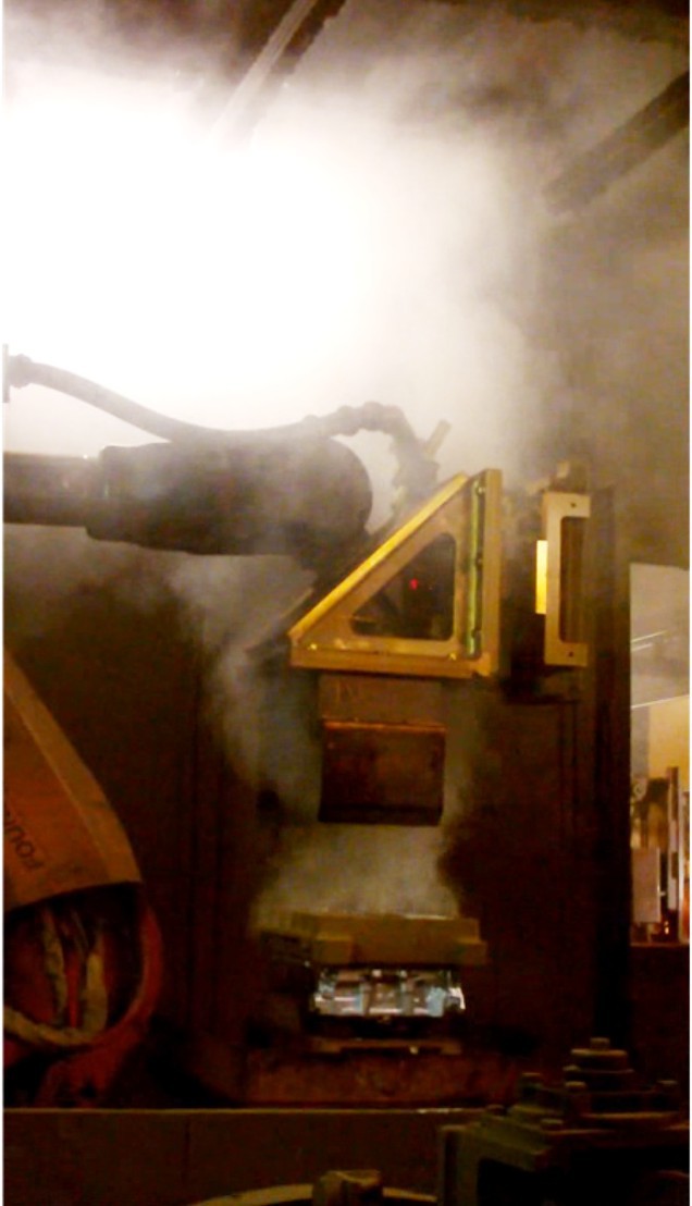
Well, this smoke comes from sand cores forming cylinder head cavities like the water jacket, intake and exhaust channels. In our case sand cores are made using organic resin. This burns with thick smoke when the automatic ladle pours 700°C molten aluminium into the die.
As temperature of the aluminium decreases, sand cores get hotter and hotter and thus they generate more smoke. The amount of smoke increases suddenly when the die opens and smoke can finally escape through all surfaces of the cores into the atmosphere.
Smoke generation is part of the technology here as well. On the other hand the challenge for the foundry was that productivity had been increased so much in the last decade that the extraction system was unable to cope with the increased amount of smoke. The foundry had to think about developing the extraction technology to match a future production volume larger than the current one.
However, the cleaning capacity of the filter is finite. The company did not plan to sink a couple of millions into a new filter. So the existing filtering capacity had to be redistributed, more efficiently used. Here comes CFD simulation in the picture.
Optimising extraction capacity
We got the job of redesigning covers and extraction systems of the casting machine by using CFD simulations. The set aim was that – in an optimum situation – no smoke should escape from the casting machine. At the top of all that we had a limited 8500 m3/h per machine extraction volume flow at 60°C air temperature.
When working on a project of this magnitude, the first step is to determine the initial status of the machine’s smoke extraction capacity and to reproduce it in a simulation. This way we have a set of boundary conditions in the simulation and a good quality CAD geometry which provide the foundation for creating new extraction configurations. Also we have a common ground to compare new versions to the original.
We chose the casting machine producing the heaviest cylinder head as a test bench. We built its 3D CAD geometry and shot several videos of full casting cycles. The picture below shows the casting machine from the front. The size of the operator in black well represents the machine’s dimensions.
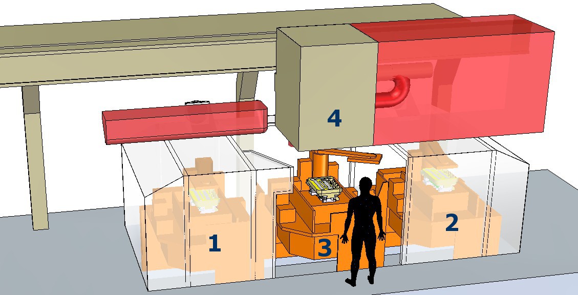
For the sake of visibility I made the steel sheet metal structure of the casting machine’s extraction cover transparent in the picture. This way you can also see the two orange coloured dies with castings in them underneath. In the simulation model we created four important positions where castings emit smoke during the casting cycle. Three out of four are in the operator’s level of work. The fourth is in the brown box of the automatic manipulator 2m above ground level. The manipulator has smoke extraction as well.
Red parts show areas in which from time to time auxiliary machinery are at present. So we had to avoid these areas while thinking about modifications. On the left there was the automatic ladle. Right hand side was the manipulator which removes freshly cast cylinder heads from the die.
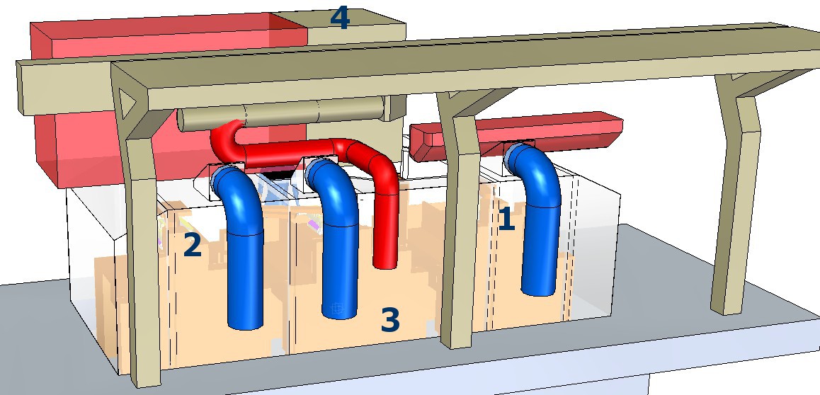
In the picture below the blue coloured extraction pipes are at the rear side of the casting machine. These ended in rather small extraction hoods on top of the machine cover. There are three of those small hoods in the original design. The bright red pipe – slightly smaller than the other three – is the one that extracts smoke from the manipulator box.
Videos of the casting cycle recorded how much smoke escaped the extraction cover and where it entered the atmosphere. Videos also showed how long a casting cycle was and how long normal or intensive smoke emissions lasted.
The four numbered casting and smoke genereation positions were results of a rational simplification. In real life in this casting machine there are only two dies and two castings at present in one time. The dies however move synchronised in a horizontal plane. They switch places in front of the operator, who is standing in the middle, at the open space of position Nr. 3.
Geometry is not moving, smoke is
Though in SC/Tetra it is possible to make the dies move, we decided to have the dies standing still. We make only the location of smoke generation change instead. The four numbered positions represent the stations where the moving casting would emit smoke in a casting cycle. Casting models placed in each of the four positions generate smoke in the simulation. I syncronised smoke generation in the simulation with the smoke generation cycle in the videos.
Pictures below show the defining smoke generation positions of the casting cycle. Blue surfaces show generated smoke.
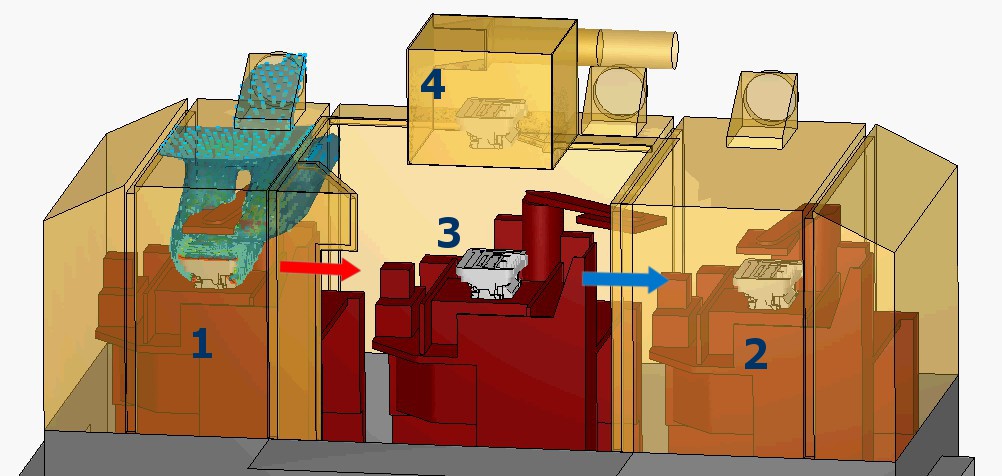
Red arrow in the above picture shows that in the next stage smoking casting of position 1. will move to position 3. But only after the automatic ladle fills the die in position 3. with melt. This die containsthe cores only at this moment. After it is full with liquid aluminium it muves to position 2. I show movement of from position 3. to position 2. with the blue arrow. The die freshly filled and moved into postion 2. will start smoking with normal intensity.
In the 2nd stage of the cycle extraction system has to handle two smoke generation positions as shown on the picture below.
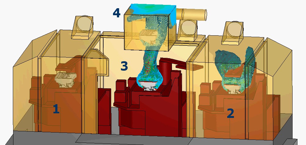
In position 2. the casting is at the beginning of its solidification and emits smoke with normal intensity. On the other hand the casting that moved from position 1. to position 3. is at the end of its solidification. Waiting for the die to open, sand cores are really hot and the amount of smoke emitted is steadily increasing. Die opens in the next stage which I show in the figure below.
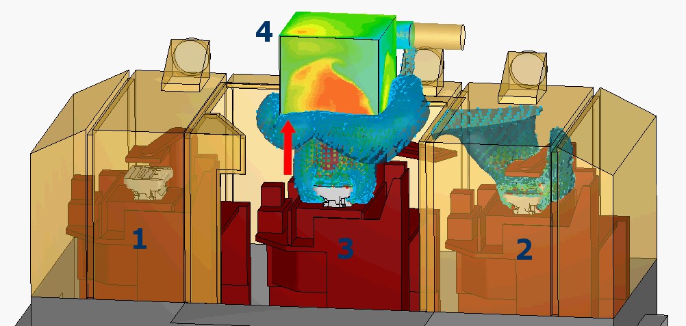
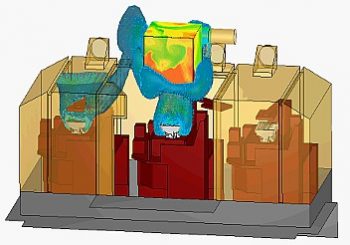
When die opens in position 3., intensity of smoke generation is suddenly 3 times more intensive than under normal conditions. The extraction box of the manipulator above position 3. is unable to handle such amount of smoke. Neither in the simulation nor in the reality. It is clearly visible in the picture above that a blue cloud of smoke escapes at all sides of the extraction box.
The manipulator will remove the intensively smoking casting from position 3. in the direction of the red arrow into position 4. The extraction box on the other hand stays where it is, not sinking with the manipulator arm. Simulated smoke generation ceases here because manipulator moves to the right side and places the casting to the next processing station.
The casting cycle continues and position 2. emits normal intensity smoke while operator places fresh cores into the empty die in position 3.
Red arrow in the next picture shows that in the coming stage of the cycle, the casting in position 2. smoking with normal intensity will slide to position 3. At the same time die in position 3. after receiveing molten aluminium will slide into position 1. (blue arrow) and start smoking with normal intensity.
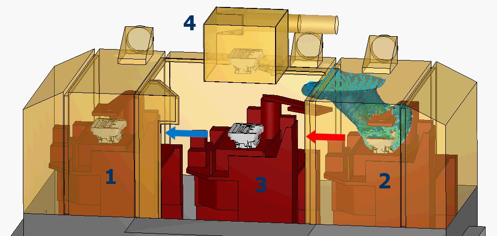
In the final stage die in postion 3. opens, high intensity smoking happens and after loads of smoke escaped the extraction box of the manipulator, the whole casting cycle starts over again. Here is an animation of smoke generation in the whole cycle:
All the smoke these three extraction pipe connections are not able to collect, goes into the workshop air.
This is a rather unpleasant situation. The first problem is that smoke from positions 1. and 2. escapes under the cover at the height of the operator’s face. The second is that there are several other machines with a cover like this. Their emitted smoke fills the workshop air quite fast. This leads to the requirement that all of the smoke must be kept within the casting machine cover. And also the extraction system connected to the cover must be improved so that it is capable of collecting all the smoke of an even faster pace of casting production.
The next part of the case study is about how we did it and how the new casting machine cover looks like. Click here for Part 2.