In the previous part I showed how we made the smoke extraction CFD modelling of the original system of the casting machine. That machine produced many hundreds of cylinder head castings in a shift. In that simulation, which represented the first step of the development project, we created the characteristic, time dependent pattern of smoke generation and validated against real life operation of the machines. The thick white smoke the casting assembly emits has to be handled by an extraction system which is connected to the machine cover.
Smoke extraction could not keep up with production increase
Productivity of the factory has increased much since these original machine covers were installed. The old extraction system was not able to keep up with the increased pace of smoke generation. The extraction system had to be redesigned and rebuilt fast.
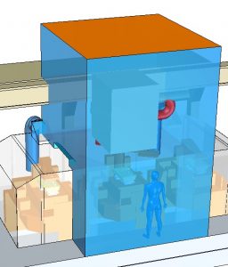
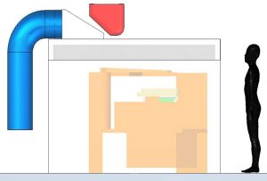
The picture on the left shows the big blue volume that represented a portion of the surrounding environment into which smoke could escape. The top orange coloured surface of this volume was the place where we measured concentration of smoke in case of the original and all modified cover versions. This concentration was the criterion upon which the efficiency of a new extraction arrangement was judged.
The smaller the concentration was and less smoke escaped the cover, the better.
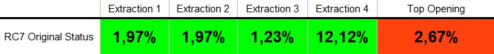
Concentration data of the intial condition
The table below shows simulated concentration values of the original extraction system. The „Top Opening” coloumn contains the concentration of the escaped smoke, measure on the orange coloured surface. 0% would mean no smoke is at present, this is our aim for the „Top Opening”. The values in the „Extraction 1-4” coloumns tell us concentration of smoke extracted by the four pipes connected to the cover.
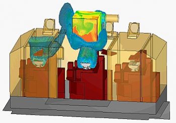
These concentration figures belonged to the original structure. The flow pattern below shows results of the smoke extraction CFD modelling of the old design:
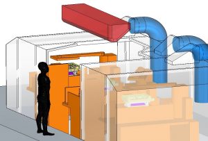
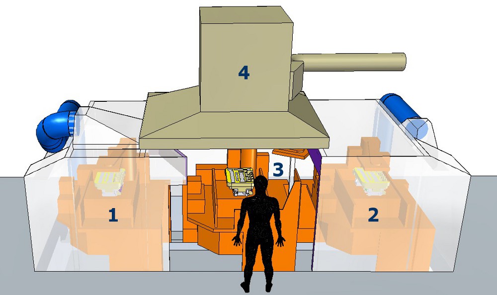
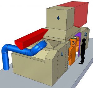
While designing the new extraction system and machine cover we had to keep many restrictions in mind. These seriously limited our freedom to make changes. Well, first there was the automatic ladle, which could just slip above the machine cover. It could not be raised any further. Pictures below show the space the ladle occupied while in motion during casting cycle. This space was off limits. Our only luck was that the ladle took this space for only a short period of time in each cycle and it parked away from the machine otherwise. It also moved away by the time the manipulator arrived above casting position 3. This meant that the ladle was not in the way of designing a larger manipulator cover.
Could not change some components of the machine
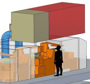
But all this was true for the automatic manipulator too, that removed the freshly cast and smoking cylinder head from the machine. It had its own extraction hood taking much more space than the ladle. We had to review its design because it was not very effective. That meant we would loose even more space because of the enlarged manipulator extraction hood. On the figures below the red volume shows the space the manipulator takes while moving during a casting cycle.
Extraction pipes meant restrictions too. Master extraction pipe was in the basement under the machine. These pipes had to stay there and we had to design their new connection to the new cover so that they did not interfere with the moving part of the machine. Not to mention the fact that these pipes had to be in easy reach for maintenance and cleaning.
Our general aim was to place smoke extraction features as close to casting positions as possible and to build in extraction hoods with the largest possible volume.
The best performing new manipulator design
We tested more than ten versions using CFD simulation for each of them. The solution below had the best performance in terms of concentration values.
We enlarged the extraction hood of the manipulator to cover the whole opening above smoke release position No3. We could easily do that because the ladle and the manipulator never took the same place at the same time above position No.3. The flexible pipe that extracted smoke from the manipulator hood was repositioned to its right side. It was necessary because we could not place the same new extraction hood at position No.2 as in position No.1. We knew No.2. could not be so effective as No.1.
New extraction hoods and new pipe routes
Important change of the new extraction system was that we abolished one of the original extraction pipes connected to the main machine cover. It was totally inefficient in its original position. We redistributed its extraction capacity to increase extraction from manipulator hood.
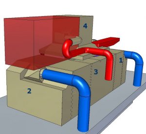
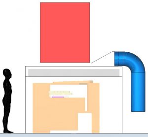
Above position No.1. we managed to install a proper sized extraction hood on top of the original machine cover. This hood had an inclined side towards position No.3. This helped guide smoke into the extraction pipe connected to the side of the new hood. As you can seen on the above left picture, the extraction pipe was led behind the machine in a trench made at the top corner of the original cover. From there it could connect to the main extraction pipe in the basement.
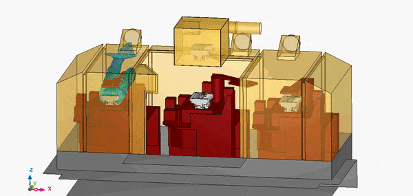
In position No.2. we had no chance placing the same elevated extraction hood above the casting because of the manipulator. Even the original manipulator cover slid 10cm above the machine cover, and the new grew even bigger in area to cover the whole opening above position No.3. So we decided to place a smaller hood approaching the casting from the side. But we turned it towards the die and sized it so that it could be as close to it as possible. Extraction pipe was led back in a similar trench like on the other side. Below is the animated result of the smoke extraction CFD modelling of the best performing design.
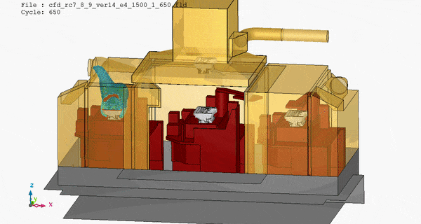
Smoke concentration of new design speaks for itself
Even the animated results showed that way much less blue plume (representing smoke of course) escaped than in case of the original configuration. Concentration results just confirmed that too.
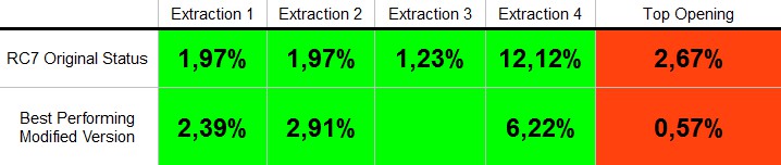
If we compare the best performing modified and the original extraction systems we see a concentration rise in extraction pipes No.1-2. This means that their smoke extraction efficiency has increased. Extraction pipe No.3 ceased to exist as it did not performed well. We redistributed its flow rate among the other three extraction pipes in a way that we doubled flow rate extracted through pipe No.4.
Concentration of pipe No.4. decreased because more smoke is mixed in with much more air. Concentration of Top Opening decreased by 79% but it did not become 0%. It was so because of the less efficient extraction at position No.2. Some smoke could escaped in the gap between machine cover and manipulator hood.
Results way above expectations
The new extraction system on the test casting machine surpassed all expectations. It was able to handle non-standard situations like die opening (intensive smoke release) while the casting was still under the machine cover instead of in position No.3.
Plant design specialists of the foundry made some minor adjustments. They fine-tuned the concept by using every available inch so the final design did not let any smoke escape the extraction system. Air quality of the foundry improved significantly.
This particular foundry spent tons of money on rigorous analysis of risks. They did not spare neither time nor resources to consistently eliminate all possible air contamination. And they were open minded to use innovatiove methods, among them our smoke extraction CFD modelling technology. Fresh air supply was also improved to suit changed extraction conditions. When the whole system is up and running at full capacity, even 4 million cylinder heads would mean no challenge.
Dr. Robert Dul