
Modern day comfort like temperature and humidity control in buildings require high-tech heating, ventilation and air conditioning (HVAC) machinery. As rain and sand are regular additives to air, HVAC engineers use louvres to keep the unwanted bits out. To help HVAC engineers we have worked out a louvre performance simulation method that can predict the most important features of this building element.
So louvres must keep rain and sand out but at the same time these should not mean too much resistance to air flow. Of course standardised ways exist to measure, test and calculate louvre performance. BS EN 13030 (for pressure loss and rain) and BS EN 13181 (for pressure loss and sand) set these. But what if the HVAC engineer has a louvre design that combines an aesthetic and a performance louvre into a non-standard setup?
Do not go for the looks only
It looks awesome but pressure loss of the combined system should be low enough to fit the air flow rate of the machinery it is supposed to supply. How to make sure it will work fine? Test it? Sure, but what if it needs changes because pressure loss is too high? Test again after a design change? Well, fluid dynamics simulation that reproduces the standardised testing process is a much smarter move.
This is why Conttego UK, a professional supplier of architectural facade systems got in touch with us. They wanted to know how big the pressure loss of an aesthetic and a performance louvre would be if placed behind each other.
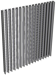
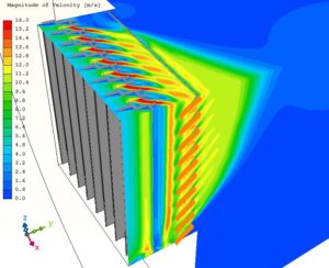
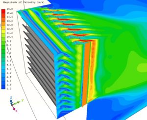
The aesthetic louvre was not previously tested, no information was available about its pressure loss figures. However, we knew the performance louvre supplier and we could find its data sheet showing the most important parameters. Figures below demonstrate the standardised 1m x 1m test louvre assemblies in their designed orientation.
Simulation geometry free from test rig limits
When a louvre is tested in real-life, the test piece must comply with the rig’s own features. Louvres must have a frame so that the test assembly can be mounted on the rig. We did not need such intricacies. We could use the whole 1m x 1m standard cross section for the louvre blades if we wanted to.
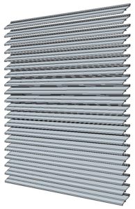
We call it performance because it lets as much air in as possible while keeping some of the rain out. The client was interested in pressure loss only, water protection performance was not part of this project.
Our team made the simulations the exact same way as a real-life test would go.
Louvre performance simulation according to BS EN 13030
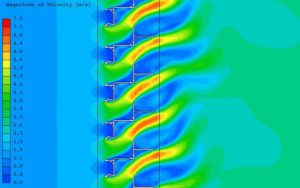
We placed the 1m x 1m test pieces in the 3D CAD model of the test rig and loaded up into the CFD simulation tool. Then applied the same boundary conditions as a real-life test would have used. We simulated entry and discharge conditions. Also simulated each louvre layer separately and behind each other to have the full scope of results.
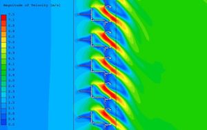
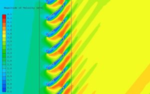
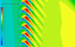
For the entry condition, the performance louvre had a Ce=0.457 pressure coefficient catalogue value. According to louvre performance simulation data, our setup resulted in a Ce=0.43 pressure coefficient for the entry case, which gives us 94% accuracy. Not bad at all.
Apart from the entry and discharge coefficients, it was a matter of minutes to get K-factors and to visualise pressure loss dependency on flow rate.
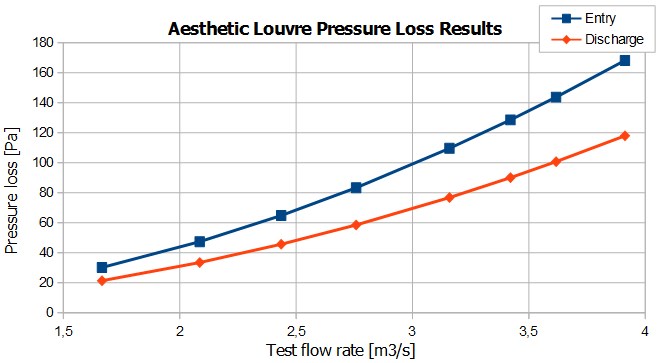
These curves show that the entry setup has higher pressure loss than discharge one. The bigger air spped is, the bigger the difference between the two setups will be. It was a challenge because behind one section of the facade was an air inlet, in need of loads of fresh air.
Results in a day
We presented all performance data of this non-standard louvre setup within a day. As a result HVAC engineers could decide how to handle the situation if the louvre system did not bring in good results.
Our louvre performance simulation method is accurate, fast and able to provide full performance testing including water or sand protection. Fluid dynamics simulation of non-standard building elements has the flexibility to run several design changes in a matter of days. A louvre pressure loss simulation can go into the very details of showing the effects of each part that makes a louvre. In this case study we investigate how gaps, blade holder clips can influence pressure drop of a design. If you are interested in the effect of using different turbulence models, you will find some data about that s well.
So just let the sunshine in, CFD simulation and computers as a virtual test bench can handle the rest.
Dr Robert Dul