You may well remember from the previous episode of the servo motor electronics CFD simulation that we had a small vertical pcb card with two silicon chips, which were feeling quite hot under the casing. These chips nearly reached the blazing 90°C when the ideal would be 60 or below. I had to do something to reduce their temperature. The original design criteria stated that no fans to be used due to noise issues. So here is what I tried as the first step in the design process.
Video showing simulation results of the design change
Check out the video below. It shows the whole process of how I saved tremendous amount of time by reusing the simulation settings of the initial design. The video also shows how I made sure the meshing process took as less effort as possible. The log files I created would speed up meshing of future design changes.
First design change in the development process
I relocated the vents both on top and the bottom, but I did not change the size of cutouts. Just pushed them a bit closer towards the front edge of the casing. My aim with the relocation of the top vent was to provide an easier escape route above the vertical pcb card for the hot air.
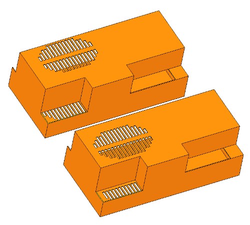
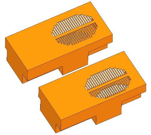
As far as the bottom vents are concerned, I relocated them to fit the array of the small chips on the bottom card. Again, to provide a better entry point for the fresh air.
![]()
With the casing removed you can see the other change in the pictures below I made to help reduce temperature of the wormest chips in the whole assembly. These two small chips on the vertical board reached the blazing hot 90°C. This was too bad as the ideal would be 60°C or below.
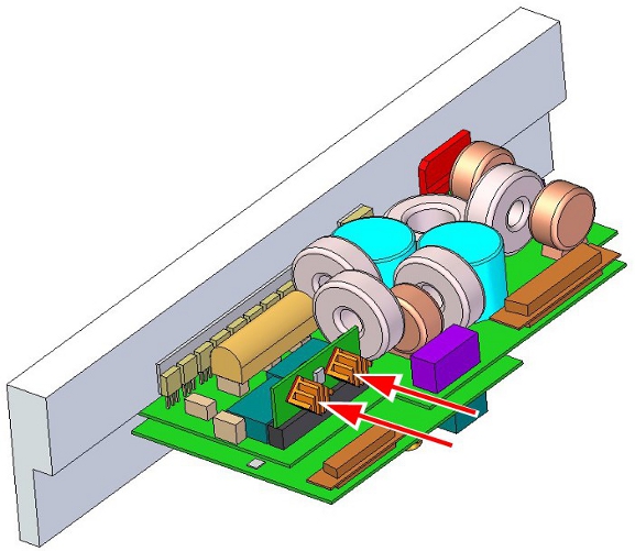
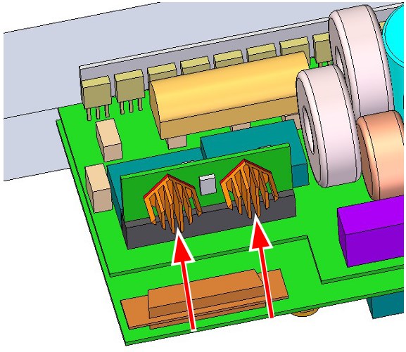
The two red arrows point at the small heat sinks I installed to both of these components. My aim with the heat sinks is to add mass with good conductivity, so I made these out of aluminium. And I also arranged the gaps between the fins to be vertical to allow easy air passage.
I implemented the above geometry changes quickly. But with every design change the real challenge was to spend as little time with the simulation setup as possible. This assembly had 86 separate components, all of them had names that did not make sense at all. This is why in the initial design CFD simulation setup I had to go through all parts one-by-one to figure out which had thermal design power boundary conditions on them.
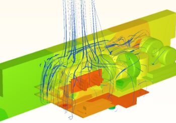
Results are predicting temperature decrease of critical components
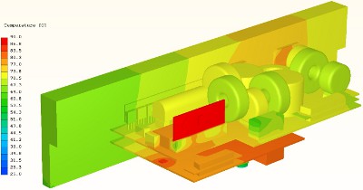
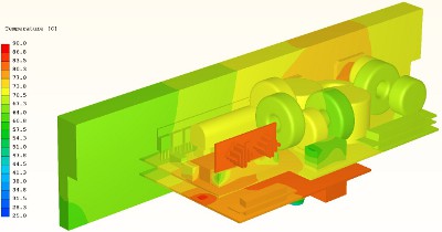
Design changes resulted in decreasing temperatures of the critical chips on the small vertical card. It is definitely some progress but still a bit far from the desired 60°C temperature the designer should aim for.Temperature of the small chips in the new design is 83°C compared with 89.5°C of the original.
But realistically this is just the first step in the thermal design and optimisation process of the servo controller electronics. Thermal CFD simulation helps engineers by pinpointing critical areas and enables finding the most suitable cooling method without waiting for prototypes.
If you have any questions regarding this electronics CFD simulation or have a recommended design change to simulate, let me know. Please get in touch by clicking the button below or in the video’s comment section.
![]()
Dr Robert Dul