When thinking about electronics, all of us would mention computers, mobile devices or electric cars. However, from electronics thermal simulation viewpoint there are some really nice examples among industrial applications as well. The subject of this application example comes from a medical imaging machine. Its job is to control several servo motors of the patient table. It works in a closed compartment and it needs a well designed air ventilation system to ensure that temperature of delicate electronic components stay below the maximum.
Unfortunately this particular casing design has some issues.
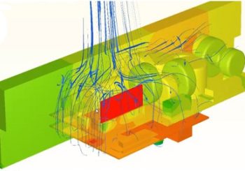
Electronics thermal simulation of the intital design
Take a look at the video below if you would like to know what these issues are and why they are there. But this video shows much more than that. It reveals how I have made this simulation in SC/Tetra including setting boundary conditions and mesh parameters. I am showing the whole workflow I use for electronics thermal simulation projects. Please let me know what you think in the comment section of the video.
Air flow design issues
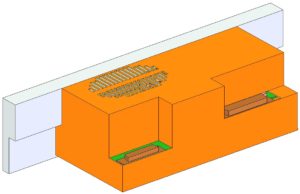
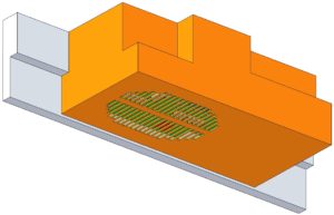
There are two set of vents on the casing: one on the lower part and a smaller one on the top. The pictures below show vents arrangement.
When we remove the orange 1mm gauge steel sheet metal protective casing, two main printed circuit boards come to light. Especially the upper bigger one is packed with components and it even has a tiny vertical board with two silicon chips shown red in the picture below on the left. The lower PCB is smaller but has more microchips: the red bigger one and small flat ones coloured in grey.
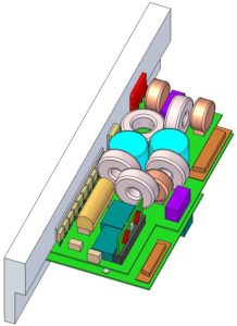
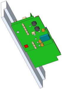
The big block part is there for a good reason. It is an aluminium cooling block that helps transfer heat from a series of diodes on the left side of the upper board. This aluminimum block gives structural rigiditiy to the controller and it also has mounting points to fix this unit to the patient table subframe.
Workflow with electronics thermal simulation
To get to this point in the design process, an electronics engineer and a CAD engineer had to cooperate. They have created the 3D CAD model you can see above. Normally, as next step, designers would send the documentation to a prototype workshop. Then an extensive testing period would start and it would bring up an issue or two.
But not with this one. These designers would check thermal behaviour first and they would send the model out to us to run an electronics thermal simulation. And instead of a prototype, which is definitely not cheap and slow to produce, the simulation would bring up the issues and the possibility to solve them much faster.
Dr Robert Dul