I surely said this before but if you are so fortunate to do fluid dynamics simulations as your profession you can always learn something new. Controlled cooling of cylinder head castings after solidification? Sounds cool! Simulation of wall erosion in a glass melting furnace? Exciting! Simulation of 2-phase flow within a Centrifugal Partition Chromatography (CPC) machine and design of a new cell shape? The mother of all simulations, though I never saw such a machine before. And I just guessed how complex chromatography CFD modelling could be when I met the young and talented chief innovation officer of RotaChrom Ltd.
The mother of all CFD simulations
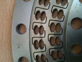
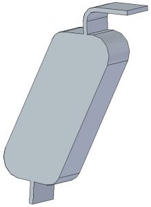
The CTO wisely put a metallic disk on the table when we first met. A disc full of precisely cut holes in it. If you are a petrolhead like myself you would say this was a disc brake with internal cooling channels. But the holes were elliptical (like on the picture on the right) or rectangular with rounds in the corner, not cylindrical. The usual round holes around the special ones are for bolts to press and hold together an assembly made of many such discs. This assembly forms a long single channel of cells. My introduction to how a CFD service like us could help with chromatography happened while sipping a lovely pint of Guinness.
What is Centrifugal Partition Chromatography?
The aim of the kind of chromatography (CPC) we were dealing with was to extract and thus purify molecules solved in fluids. We call these purified molecules fractions.
To do this we need two immiscible fluids (phases). One of them contains all the molecules (solutes) we want to extract, let’s call this phase the moving one. Let’s call the other phase the stationary one. Names of phases hold some additional info on how the procedure works. At the beginning of purification, cells of the machine (like the ones on the above figure) are filled with stationary phase and discs containing the stationary phase are rotated around their axis. After that moving phase is pressed through the system of cells.
Stationary and moving phases do not fancy each other. They do not solve in each other (immiscible). One of them is hydrophilic, the other is hydrophobic and their density is different too. The moving phase – because of cell shape and centrifugal force – breaks apart into very small droplets which make contact with the stationary phase in the cells.
Molecules we are searching for have a distinctive feature which is their solubility in stationary phase. Stationary phase works like a special filter which slows down our molecules according to their solubility. If a molecule is highly soluble in stationary phase then it takes more time for this molecule to travel through the chain of cells compared to a molecule poorly soluble in stationary phase but highly soluble in moving phase. The molecule that has the worst solubility in stationary phase runs through the system in the shortest time. The machine can catch this molecule first at the purification process.
The machine measures molecule content of moving phase and it detects when a molecule starts appearing and running out. These molecule fractions are collected separately with the slowest molecule leaves the chain of cells last.
Uncharted territory for CFD simulation
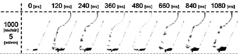
Nobody in the past investigated what happens in a cell in terms of flow phenomena. However we managed to find a pretty good reference [1]. Adelmann et al. used OpenFOAM to model flow features within the cell. But the real value was that it contained a comparison of simulated and measured results. Measurements (I am calling these PIV rotor tests from now on) were made on a test disc using a high-speed camera so that flow patterns could be recorded and analysed.
Setting of forces like this has several advantages but I believe there is one disadvantage as well.
Pros:
- the required flow field always “happens”, there are no flow effects that disturb or slow down convergence,
- a converged solution can be reached in a fairly short amount of time: under 300 ms it is there even for high RPMs and flow rates,
- number of required iterations to reach convergence can be quite small,
- mesh can have a smaller resolution (element size can be bigger).
Cons:
- I believe this solution is literally forced, meaning that this setting pre-determines flow features. Before a single iteration was even started.
One important disadvantage we had to get rid of
We thought this disadvantage would have its fingerprint on solutions if we wanted to develop new cell shapes. So we did even the first validating runs with real rotating motion. Only gravity was set as an external force. Rotating motion generated the other two forces automatically.
I mentioned above how important roles the two phases had so it was not even a question that we would set up a transient two-phase CFD simulation using VOF (Volume of Fluid) method. Adelmann et. al. examined several solvent systems, we used ethyl acetate (stationary phase) and water (moving phase) pair since this system has well known material properties and phase behaviour.
During validation project many of the moving phase flow rates and rotational speed combinations stated in [1] were analysed, mostly those were chosen for which both simulated and measured data and photos were available.
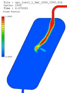
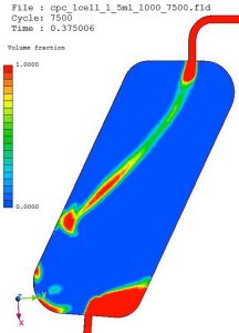
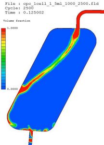
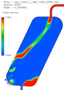
Take a look at the results for 5ml/min moving phase flow rate and 1000 1/min rotating speed. Coloured pictures show results of SC/Tetra simulations, black-and-white ones show results of PIV tests of [1].
What numbers and shape to look for
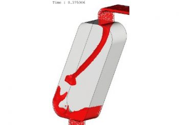
What experts in CPC use to decide whether a solvent system and a cell is efficient enough, is the shape moving phase (shown red on the picture on the right) has when entering at the top and while flowing in the cell. If they are lucky enough to take a look at it somehow. Without chromatography CFD modelling it would be just the same old trial and error kind of development. Anyway, a cell does its job well if the entering phase jet breaks into small droplets fast, the sheet of moving phase is not bent towards cell wall and only a small amount of it remains at the bottom of the cell.
We aim to maximise contact surface between stationary and moving phases. This aim is adversely affected if sheet of moving phase is bent too early by Coriolis force towards cell wall. The picture on the right shows a result which is acceptable in terms of moving phase sheet shape for this given cell. The red moving phase is not bent that much and there is not much moving phase collected at the bottom of the cell near the outlet. Compared to PIV rotor test results it was clear that in SC/Tetra simulations moving phase sheet was less bent and volume of residual moving phase at cell outlet was almost the same both in terms of quantity and in shape. When increasing cell RPM while keeping moving phase flow rate unchanged we saw an even less bent moving phase shape. Volume of residual at the bottom also decreased.
![<i>Results of PIV rotor CFD modelling for 5ml/min and 1400 1/min; Source [1]</i>](https://www.cfdengineering.co.uk/wp-content/uploads/2017/12/39_5mlpmin_1000rpm_375ms_2-190x300.jpg)
Results of PIV rotor tests for 5ml/min and 1400 1/min; Source [1]
Let’s look at an other parameter set
So far so good. Time to put the case on the table in which flow rate of moving phase was 20ml/min together with 1000 1/min rpm. In the Adelmann article there was a figure which compared PIV test results and OpenFOAM simulations for 21ml/min and 1000 1/min rpm. You can see this on the left side of the figure below. On the right we have chromatography CFD modelling results from SC/Tetra for 20 ml/min flow rate at 150, 350 and 750 ms after starting simulation.
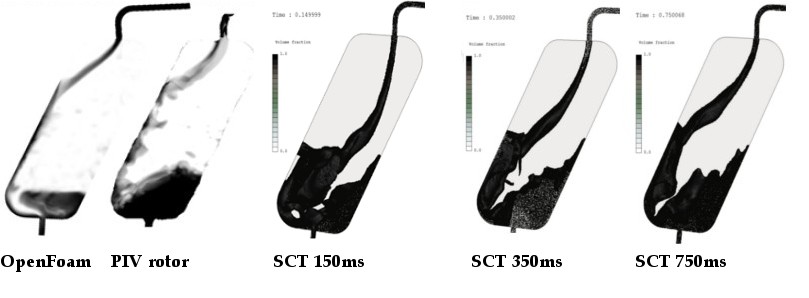
When comparing OpenFOAM and PIV rotor test results one can notice the difference in quantity of residual moving phase near cell outlet. Namely there is more moving phase at the bottom in the PIV test. On the other hand the location where moving phase sheet touches cell wall is almost identical.
When comparing PIV rotor tests and SC/Tetra simulations you can clearly see that residual quantity, shape and location are very similar. But there is a difference in the location of wall contact. SC/Tetra simulation results also demonstrate changing shape of moving phase sheet as simulation went on. This meant that bending of sheet increased during our 750ms simulation time while quantity of residual at the bottom remained almost the same.
What can we derive from all this when we want a workflow that leads us to a new and more efficient cell shape?
The precise solution takes longer than the forced one
Using real rotating motion for the chromatograph CFD modelling takes much longer to get to a steady and developed flow field than for a simulation using forces set on mesh elements. Because of that a real motion simulation requires much more iterations to run. But the first good news is that it is capable of more accurately estimating residual moving phase volume at cell bottom. The other good news is that SC/Tetra simulations performed well in calculating bending of moving phase sheet. Because bending always happened when PIV rotor tests showed it and extent of bending changed the proper way when flow rate or rpm parameters changed.
So for us it was worth using real rotating motion despite the longer simulation time compared to direct force setting. In return we had a workflow that gave us more accurate results that could forecast the effects of the tiniest change in cell shape.
Later in the chromatography CFD modelling project we proved that our way of doing this brought satisfactory results. In less than a couple of months we could develop a new cell shape, build a test machine and measure purification efficiency. It turned out that this cell could purify molecules twice as fast as a competitive one. Obviously RotaChrom patented the hell out of it.
Development of new cell shapes and CPC machines never end at RotaChrom. And I am just as excited to learn and develop something new as 3 years ago when our cooperation started.
Dr. Robert Dul
[1] S.Adelmann, C. Schweinheer, G. Schembecker: Multiphase flow modeling in centrifugal partition chromatography; Journal of Chormatography A, 1218 (2011) 6092-6101.