When car park ventilation systems are designed, building regulations in the UK set two major requirements. The designer should provide at least 2.5% of the floor area as free opening. The designer also should choose a mechanical ventilation system that is capable of at least 3 air changes per hour. A car park ventilation CFD simulation could reveal however that apart from the regulation numbers there are other factors that influence performance.
Fluid dynamics simulation of mechanical ventilation systems can definitely give a better insight into how efficient fresh air supply is.
Undercroft car park as virtual test site
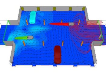
This small undercroft car park has an area of 320m2. Togehter with an internal height of 2.4m this gives 768m3 air volume. Black arrows in the figure below are pointing at the fans I chose for this application. Each fan is moving Q=0.94m3/s air and are special low profile types developed for applications where internal height matters. They are facing in the same direction so when these are operating air will flow in on the right (blue arrow shows the entering fresh air) and will leave the premises left where the orange arrow is.
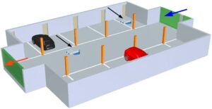
towards the outlet (orange arrow)
Let’s do the building regulations maths. The inlet opening is 13.2m2, the outlet opening is 14.4m2, together 27.6m2. These are louvred ones for privacy, so let’s suppose only 50% is open which gives 13.8m2 free opening. A 320m2 floor area requires a 8m2 opening so this point is check.
As far as air change per hour (ACH) is concerned, each fan can do Q=3348m3/h. Two fans do 6696m3/h which in theory gives us 8.71 ACH (6696/768). 3 ACH is the necessary minimum so an other check there too.
At this point we may lean back and be off for a beer. But a CFD simulation can also reveal that other factors like position of fans do have a say in this matter.
Let’s look at more than just one fan arrangement
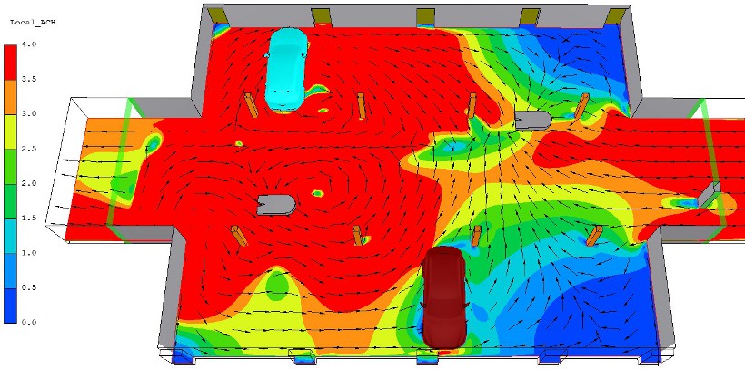
The pictures below show air velocity at 0.8m and 2.1m above ground. Air velocity is below 0.1m/s almost everywhere except in the fan plumes. Incoming average speed is only 0.06m/s which results in Qin=3110m3/h incoming flow rate. This gives only 4 ACH instead of theoretical 8.71. Still above the required 3 ACH but why different from the hand calculated figure?
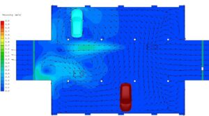
It is so because only the fan on the right draws fresh air in, partially, as some fraction of its duty is spent on circulating old air. The fan on the left only moves air the right fan is passing on to it. As ACH depends on air flow velocity, we can use the simulated velocity values to calculate local ACH patterns. This enables us to look into the air flow charactersitics of the car park. And also to get more data out than just a single averaged ACH coming from a hand calculation.
Comfort parameters are less important for a car park as they would be for an office building. But we can use them to know even more about the flow characteristics. Local age of air shown at 2.1m above ground level adds an other perspective to what we already have.
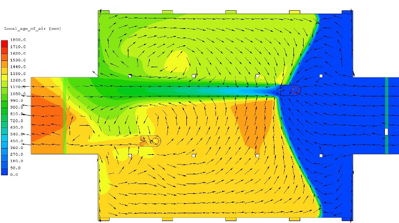
Air is fresh when it enters the fan on the right and while it gets pushed towards the outlet, it is aging as its dark green colour shows. The left fan draws air in that is already 1300seconds (21 minutes) old. From this and the fact that incoming air has smaller speed than the lightest draught a human can feel (which is at and above 0.1m/s air velocity) you can see this ventilation is quite slow.
Easy to change ACH even using the same fans
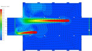
Here is the velocity profile for an other fan arrangement. Fan duty is all the same, what I changed was fan location as I put both fans close to the car park air inlet.
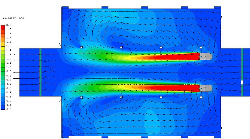
No matter how good the long plumes look, this one is not better at all as average velocity at the inlet is v=0.046m/s only. This results in 3.1 ACH, bearly above requirement. By modifying fan location I was able to change ACH by 1 whole unit. So it is really important to know how the mechanical ventilation system will perform in a given space.
Local age of air is also different from the first version as more red and orange show longer circulating air. The reason again is that these fans are standalone units, not part of a controlled fresh air ductwork. Fans also draw in air that has already aged while making big circles in the air space of the car park.
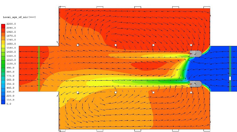
blue means fresh, orange and red mean old air
A mechanical ventilation CFD simulation can reassure the designer that the system they created would operate according to building regulations. The same numerical analysis also provides insight into how the performance of a building element (fan, aesthetic or performance louvres, etc.) can be efficiently utilised taking the internal arrangement of the space into account, let it be a car park, office or any other ventilated area.
Dr Robert Dul