Looking for an industrial equipment to show fluid flow and heat transfer simulations in a very visual way? Then a mixing tank seems to be an ideal choice. It is because motion and multiphase are all part of these machines’ daily job. Also because we can demonstrate these two interesting software features at the same time. This case study presents the recording of a mixing tank CFD simulation webinar which Dr Steff Evans from Evotech CAE and I did earlier.
Mixing tank webinar
This recoding contains loads of intersting information about how to prepare a complex geometry for CFD in MSC Apex. But if you are keen to see the CFD parts only, these are starting at 9:45′ and at 28:00′. If you have any questions, you can let me know in the video’s comment section.
Why simulating a mixing tank
The purpose of a mixing tank is easy to define. Factories use heated mixing tanks like ours in this example to increase heat transfer into the fluid as the fluid flows faster at the tank wall thanks to the motion of the mixing element. So the point is to get the heat transfer between the fluid and the heated tank wall as efficient as possible.
I have already published a case study about turbo mixers, in which we examined the effect of different water levels in small laboratory tanks. We chose a 2m3 mixing tank for this webinar, and being a real life case the original geometry contained many small parts I did not need for the CFD.
Simplifying the geometry and running the CFD simulation
The plan was that Steff handled all geometry simplifications with MSC Apex. Since this software combines direct modelling with FEA analysis capabilities it becomes a powerful design tool. The good thing about direct modelling is that we do not need the feature history of the geometry to freely modify the shape.
Steff cleaned the mixing tank model with Apex in no time and sent the parasolid model to me. From there I prepared the simulation with scFLOW. Twice.
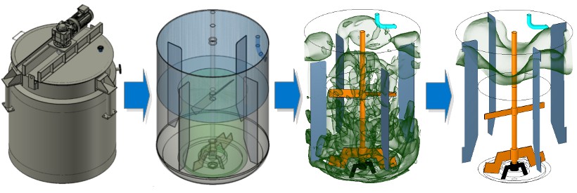
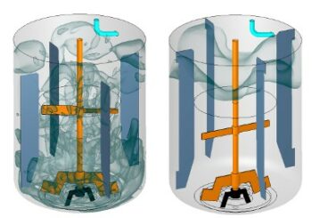
Third from left is the result of the first geometry version.
On the right is the result of the modified blade shape and location
Twice because looking at the results of the first run I asked Steff to change the shape of the mixing element. And also to reposition it so that we could have a more favourable fluid flow at the walls. It took only a few clicks for him to complete the changes. Starting from there I could also show how easy it was to use settings of a previous simulation on a new geometry.
Dr Robert Dul