In the previous part I wrote about how effective and flexible meshing had been with SC/Tetra when simulating many extraction head versions for the cylinder head cleaning project. When I wanted to analyse a new extraction head I only had to change and remesh that specific part and attach it to the main mesh again and push GO button.
Since the whole simulation domain contained 11 million elements – 6.6 million was the casting alone – this meshing method resulted significant reduction of meshing time. Because in order to create the mesh of a new version I only had to remesh a 3-4 million element piece instead of the whole 11 million element domain.
Goal is to reduce energy usage
As I wrote in Part 1. the final goal was the reduction of energy consumption of the cleaning cell. According to the new idea coming from DELTA-TECH Hungary compressed air was not blown in by hundreds of injector nozzles but using an industrial vacuum cleaner small aluminium particles were extracted from casting cavities. The Austrian original blowing type design consumed let’s suppose 12kWh energy in the form of compressed air.That was reduced to 10kWh after appling results of our simulation in 2013. A vacuum cleaner would do it in 6kWh and 8 m3/min air volume flow. So 60% of the already reduced energy, if extraction heads were properly designed.
The only way you can properly design the extraction heads is to know what is going on in them and in the cylinder head casting. Because nobody can see inside cylinder head channels while cleaning here comes computational fliud dynamics into the picture.
In order to judge wheter one version is better than the original injector type design in terms of cleaning performance we need a quantitative measure. Of course apart from the number of removed particles. But particles can only be simulated in a transient analysis that would be way too time consuming to calculate for every extraction head version.
Wall shear stress is the key
The measure is wall friction velocity that has direct connection with wall shear stress. Wall shear stress depends on friction velocity, distance from wall and kinematic viscosty of fluid and so finally on velocity near the wall. SC/Tetra calculates u* wall friction velocity which is perfect for us because where this u* is large high velocity and good cleaning performance can be expected. Where u* is small, flow separates from wall and does not remove particles that are attached to casting channel surfaces. To give you a visual example of small and large wall friction velocity I present these two photos. Also as proofs of high science in popular television programmes:


So we had the measure and to have a reference average friction velocity was calculated on each surface of the cylinder head where particles were genereated. These averages became our basis for comparing the original air injection and the new air extraction methods.
Steady-state runs first to save time
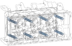
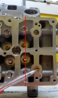
Steady-state simulations had be to run with the new extraction heads until results were better than the reference. As examples let’s take a look at some cross-sections of the cylinder head. I am showing results for an intermediate design stage of an extraction head. A red line on casting photo shows the location of the given cross section.
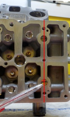
on casting
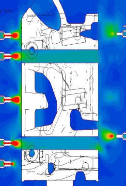
on casting
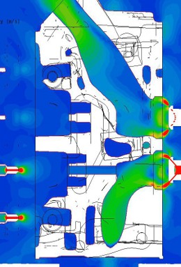
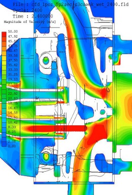
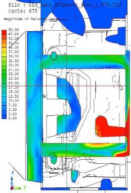
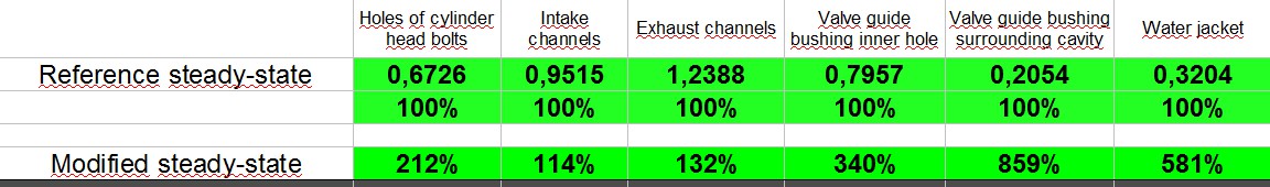
Larger flow velocity and thus larger wall friction velocity in holes for cylinder head bolts and in intake and exhaust channels clearly indicate improved cleaning performance for the new version.
The table below summarizes results of the reference and final new version.
Since steady-state simulations – without particles – showed good improvement over the original multi-injector design it was time for making things more complex and addig some particles to the model.
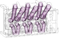
Particle cleaning simulated in real time
During particle tracking simulations I was looking for the best suitable operation timing for our extraction heads. Since the extraction heads had two or three outlets each could be opened by a valve. Valve opening times could be optimized to reach maximum particle removal performance. On the figure below blue line shows the number of extracted particles in time while broken lines show valve opening and closing times and extraced volume flow rates.
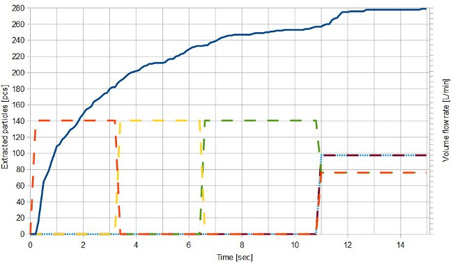
In this example valves shown by orange and yellow lines were operated first for three seconds each. On the blue line at 6.4 seconds we were at 230 extracted particles (out of 280 altogether). It is clearly visible how the intensity of particle removal decreases: curve is getting less and less steep. At 6.4 secs the valve shown by green kicks in and by 10 seconds 255 particles were removed out of 280. However blue curve became almost flat. This told us there was no point in pushing things further this way. This valve opening configuration had reached its efficiency limit.
At 10 seconds all five valves were open and all 8 m3/min air volume flow was applied in a way that valves shown with broken blue and red lines got more than the others (they are higher than the others on the graph). Particles liked the idea and started to leave the casting channels again. At 12.5 sec when things ended 279 particles were removed out of 280. Blue curve became flat, no more particles could be removed this way.
How much better than before?
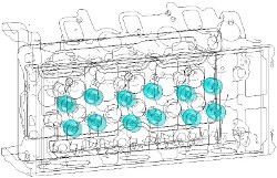
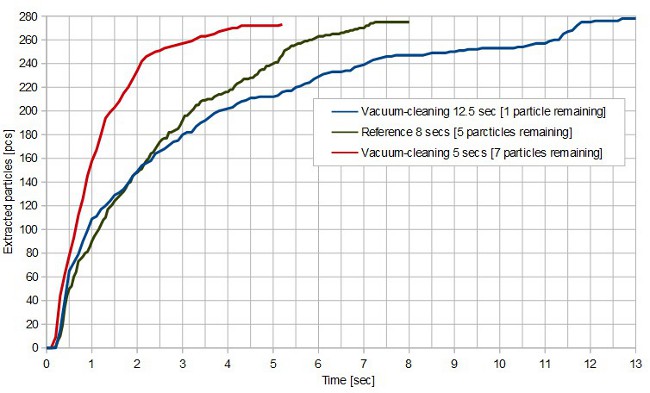
Let’s see where we are at compared to the reference. The original multiple injector design left 5 particles in the casting after 8 seconds of operation. All of them could be found in water jacket area, very hard to fully clean with air. Not a problem though because one of the next cells does cleaning with high pressure water. That usually wipes them off.
The vacuum-cleaning method left 1 particle after 12.5 seconds of operation, again in the water jacket. Being a bit slower than reference is also not a problem because cycle time is 40 secs. We are good to go this way too.
Just for the sake of curiousity we made simulations with 5secs maximum cleaning time and 8 m3/min air volume flow. The figure below shows that this does the job reasonably well. However instead of 5 particles of the reference, here we have 7 particles left in the cylinder head. If someone would be interested in reducing cleaning time, we could do it at the price of leaving some more particles in the casting.
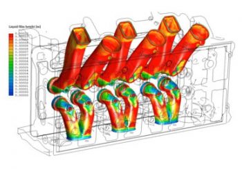
Liquid film feature simulates cutting fluid removal
Apart from the above a new feature of SC/Tetra was used for this geometry. A feature that did not exist in 2013 while making reference simulations. This feature is called liquid film simulation. The engine plant was quite interested because casting surfaces were covered with thin film of cutting fluid. They wanted to know its thickness change during air cleaning.
SC/Tetra calculates variations of the initial 0.1mm thickness based on near-wall flow properties. This video shows simulation results.
Same things as with particle removal apply to changes of film thickness. Where flow near the walls have larger velocity and thus larges wall friction velocity, film thickness reduces quickly. The initial red coloured 0.1mm film thickness turns into blue where air flow is appropriate.
Simulations made in 2013 for the largest engine manufacturing factory of the world resulted in 10000 GBP/year worth savings in energy bills for that single cleaning machine. At the beginning of 2015 in this very plant 50(!) similar machines work with the same optimized and proven parameters as the first one. Well, as I usually say, a good CFD simulation project is definitely worth the investment.
Dr. Robert Dul