Sure a Caribbean cruiser is big enough but there are bigger ships in the gas and oil drilling industry. Many of them are tankers but floating refineries are also constructed. I got in touch with one of the latter because of a project and I had the chance to commit a few simulations on a 355m long, 58m wide giant having the daught of a mid sized office block (21 metres). This article can’t say a word about the real job, but can introduce you to CFD modelling of waves and floating objects. Before running the real CFD analysis I made some tests in the preparation phase. These are quite good to show how SC/Tetra handles this complex physics.
By the way, I had the opportunity to work for the offshore oil & gas industry before. Here is the story of a top urgent top secret project.
Test complex physics on a simple model
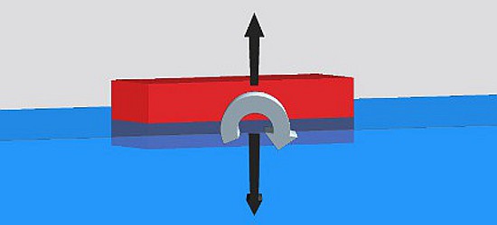
Testing of a software function always happens on a simple geometry in order to have the simulation run fast and give a chance for the problems to arise quickly at the very beginning of the project. I did not overcomplicated the model, just used a 350mm long and 125mm wide wooden block that submerged into water by the half of its 100mm thickness. The picture below shows the simulated system and the fact that I made the blue coloured water and the air above it out of 4 pieces has a significant meaning.
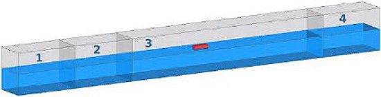
This is because we need a surface where generation of waves is defined (this is the vertical surface between blocks 2. and 3.) and volumes are needed before inlet and outlet to suppress the effects of waves (volumes 1. and 4.).
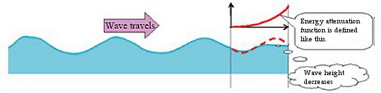
Suppression is required because without it waves hitting these surfaces start traveling back into the simulation domain and these waves would jam both the frequency and amplitude of the originally generated waves. Suppression affects energy of waves and it is controlled by a function the user can tune in a way that waves at the inlet and outlet will completely disappear.
Well, we know how to suppress waves, it is time to check if we can generate them. SC/Tetra uses WGS (Wave Generation Source) method that applies an artificial mass increase and decrease at the chosen surface that is inside the simulation domain.
Types of wave forms
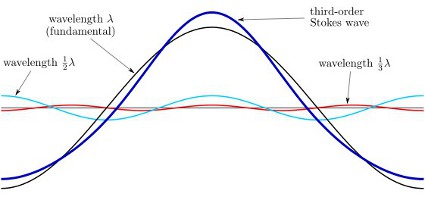
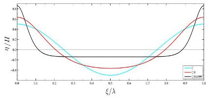
Depending on wave period and height and water depth SC/Tetra creates different types of waves like:
- 5th-order Stokes wave,
- 5th-order cnoidal wave,
- small amplitude wave,
- randomly generated wave.
Apart from using this model to test wave generation it was a perfect fit for trying two more functions. The first one was the head current, because water flew with 0.25 m/s towards the wooden block. The second one involved some restrictions of the degrees of freedom of the wooden block. Namely I only allowed it to rotate around its axis parallel with its shorter 125mm side. It could also move along a vertical line. With this I modeled the fact that the ship was anchored so no movement back and forth and to the sides. On the other hand it was capable of tilting and following the change of water level by moving vertically with it.
The result looks like this:
Floating, floating, gone
A little bit of comment on the video. The first thing the block did was to rise as much as its density and the lift force allowed. When wave generation started it smoothly followed heights and valleys. But as head current of 0.25 m/s and waves could not push it away due to being “anchored”, its front side meant resistance for the water. At some point water started flowing over it to the top surface. When the ride got bumpy so much water flew over the top that the block flipped forward and head current turned it upside down.
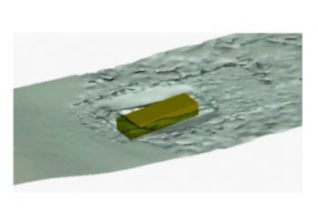
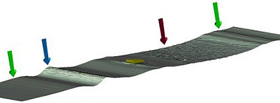
Commenting continues on the picture below where I highlighted the location of wave generation with a blue arrow. The two green arrows show the location of suppression volumes while red arrow points at an area where free water surface sinks below the level I expected. As a consequence enters into an area where I did not make such a fine mesh as I used elsewhere.
The mesh tells it all
Talking about mesh: the next figure details mesh of the block and its surrounding area. You can clearly tell apart different element type and sizes. Base mesh of water and air domain are simple. These are the areas where – theoretically- only water or air can exist. Size of elements (length of an edge of a square) there is 4 cm. Between those two „clean” areas there is the intermediate zone. This is the wave area where I generated altogether 20 layers of 1 cm prismatic elements to provide a nice and smooth free fluid surface. This is the mesh from which water surface moved out at the red arrow.
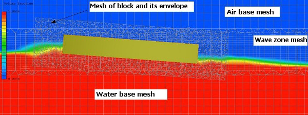
The floating block and its envelope moves in the mesh of the wave zone in a way that elements of solid material (also called as slave region) overlap the elements of fluid or gas material (also known as the master region). In such a a case the software temporarily masks fluids to solid material.
Take care when creating the mesh where you expect masking. The most important meshing rule is that mesh size of master region must be equal to or smaller than the elements of slave region namely the wood block and its envelope.
Here comes a video of the mesh while the block is in motion.
The method of CFD modelling of waves I tested here worked out perfectly for the 355m long big ship. The only difference was that it did not flip upside down at the end.
Dr. Robert Dul