My favourite trick was back at the university when the professor during fluid dynamics lectures (but you can play the same game with maths of structural mechanics) came up with a really-really long and complex equation, then he applied some conditions (saying for example that one or two parameters are neglectable thus not important next to the others) and elegantly crossed out 80% of the equation. From then on it could be solved easily. What should I do if CFD modelling with complex geometry means I need to use a fully detailed, complete in-line six-cylinder natural gas powered engine?
The same. Let me show you how.
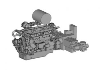
A massive gas compressor driven by a six pot engine
Some time ago I worked on a gas transmission pipeline evacuation compressor assembly. One part of the model was a beefy gas compressor driven by an in-line six-cylinder natural gas powered engine. The device itself – as its name shows – is used to evacuate gas pipelines. Sure it is not a cheap machine but as far as I know it pays itself back under 1-2 pipeline evacuations, so it is a good business for everyone.
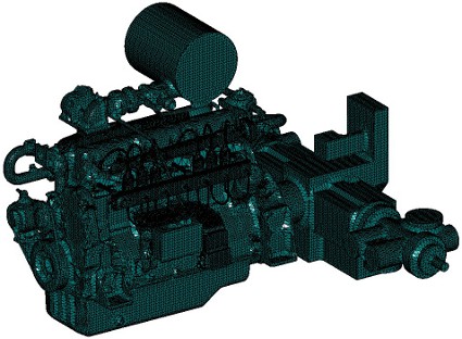
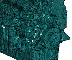
Anyway, I got the extremely detailed otherwise very precise parasolid geometry (without feature history of course) from the engineer who was responsible for the mechanics. Starting from this I needed to make a CFD simulation of the surrounding air of the compressor unit. When I say extremely detailed, I mean this:
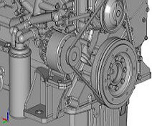
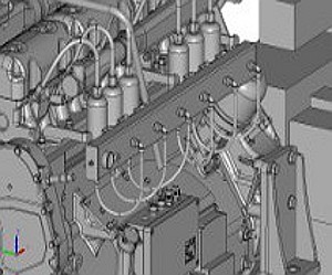
Got the V-belt, generator, fuel pipes and electrical wiring? And the infinite number of bolts? And the washers?
CFD modelling with complex geometry does not need bolts and washers
Meshing such a detailed model is almost impossible even for SC/Tetra. Not just because the small parts would require very detailed mesh with small element sizes but the parasolid model of the engine also contained some surface parts with gaps I was not able to stitch automatically and make a solid model out of them. No matter what I needed the engine as a closed volume to use it in the external flow simulation.
I could choose the path to remodel the whole engine thing in our CAD system and put that into the simulation knowing that what I do will be simple enough and 100% closed volume. But first: this would have taken too much time and second: this would have not been elegant. I know much better than that.
The simulation task itself did not require such a detailed geometry either. I needed the engine to explore air flow around it, so I needed the engine plus the parts attached to it as a closed volume but not too detailed however not too rough to represent the contour. How can I simplify the engine without sweating blood, but the elegant way like the professor did some years ago?
Wrap it up in a big sheet of cloth
This is what we call Wrapping in CFD modelling with complex geometry. As a first step the CFD software creates a grid of hexa elements (cubes) around the geometry. Of course the user can determine what cube size should be around each part. The ones I want to keep more detailed will have smaller the rest will get a bigger sized cube grid. The smaller the cube size is the tighter the sheet shape will be. The resolution of the whole engine-compressor block was 15 mm and I used 10 mm cube size just for a few but important parts.
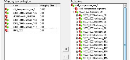
And the result is a tessellated model (like an .stl file) that contains all important details of the motor-compressor unit, makes a single closed volume that can be used further on for my simulation. Who could ever want more?

Wrapping is a jolly good tool for creating geometry of under-hood simulations. It can fill multiple cavities that you can find in electronics, headlamps, fog-lamps, etc. But this is the way I make a simplified contour of complex shaped castings like engine blocks and cylinder heads.
So if there is a task looking very complicated, have no fear. Just score out the half of it like the professor did or wrap it up like I do. It will work.
Dr. Robert Dul