Did you know that thermal management of a cylinder head had started way before it was bolted on your engine block? It was the single most important 90 minutes of its service life. It first happened when the cylinder head casting emerged from the die freshly cast, still liquid behind the thin solid outer layer of aluminium. This article tells how Computational Fluid Dynamics plays a defining part of that first, 90 minute long controlled cooling process.
From heat transfer viewpoint we face two essential challenges with regard to castings. The first one is that a certain mass of metal that corresponds to the casting, feeder and every other metallic parts of the casting assembly must be melted. The second one is that the freshly cast assembly must be cooled down on a special, controlled way and this is what we look at in this case study.
Controlled cooling with air substitutes regular heat treatment
The reason behind the engineering and timing of the controlled cooling is that with a certain cooling intensity, aluminium castings could reach mechanical properties which could otherwise only be possible with regular heat treating later on in the manufacturing process. So if a foundry could use a controlled and rapid air cooling right after casting, it could save heat treating capacity and lots of money. So this is what it is all about.
In order to check a casting cooling line, or to define cooling intensity necessary to decrease temperature of a net 22kg aluminium casting from 530°C to 80°C in 80 minutes, heat content of the casting assembly must be known. Net weight means the cylinder head only, because casting assembly contains other metallic parts like the feeder, melt intake system, etc.
Heat content vs. heat removed
Look at the whole process as two arms of a balance. On one side there is the heat content of the casting assembly, just removed from die. On the other side there is the capacity of transferring heat from the solid object into the cooling medium. In plain English – when air cooling is used – there are the positions of casting and cooling air nozzle, average velocity of cooling air, its temperature and its humidity. With other words these can be summarized as the intensity of cooling.
These two sides are characterized by one equation for each:
heat content of casting, given in Joule: Q=c∙m∙ΔT, (1)
heat flux from the surface of solid, given in Watt: Pq=α∙F(Twall-Tair). (2)
where:
c: specific heat of solid [J/kgK],
ΔT: temperature change an object having mass “m” has undergone during heat transfer [°C],
α: heat transfer coefficient [W/m2K],
F: size of surface through which heat can be extracted [m2],
Twall: temperature of surface to be cooled [°C]
Tair: temperature of cooling medium (currently air) [°C]
These two sides are connected unitwise by the time given to carry out cooling process, since W=J/s.
Heat content of the casting
Let us take a closer look at the heat content of the casting assembly. Casting assembly is made of parts as the cylinder head itself and feeder and all sand cores attached to the casting when controlled cooling starts.
We need to know the surface and internal temperature field of casting and cores either from measurements or from casting simulations. We also need mass of casting and all of its attachments. And finally if specific heat of the alloy and sand which cores are made of are also available, then heat content of casting assembly can be calculated according to (1).
As an example, let’s take a casting assembly which contains 33.2 kg metal plus 22kg sand cores and it should be cooled from an averaged 530°C to 80°C. Heat content of the casting to be removed during cooling process is 18MJ.
Since the casting assembly contains several sand cores in- and outside of the cylinder head while in the cooling process, heat content of these should also be extracted by the cooling line. In case of some casting assemblies specific parts of the sand cores are either deliberately broken off the casting, or because resin burns out of them they fall by themselves. This is the best that could happen from the controlled cooling viewpoint. With these sand pieces falling off, their heat content also leaves the cooling line and thus their heat content should not be handled any more in the cooling process.
Based on the above heat content of casting assembly to be removed by the cooling line is 18 MJ. On the other arm of the balance is the heat removal capacity of the cooling line. This capacity is determined by the elements of equation (2). Some of these elements can be influenced by the construction engineer or the operator of the cooling line.
Heat removed from the casting
Equation (2) has three parts. Let us take a look at all of them to see what influence we have on them. The temperature part, expressing the difference between wall and cooling medium has an ever decreasing influence. It is so because wall temperature has to decrease as cooling goes on. At the same time temperature of cooling medium tends to be constant. Thus their difference decreases continuously playing less and less part in our business.
The “F” part of equation (2) is constant again, since outer surface of the casting cannot be changed during cooling. Unless some more sand covering metal parts break away from the assembly and expose a bigger surface of the hot casting or the feeder.
The only part of equation (2) the engineer has full influence on is heat transfer coefficient (alpha, α).
What are the features upon which heat transfer coefficient depends? If water cooling or dry ice provide too much of cooling intensity for our aims, air-based cooling is the choice. So heat transfer depends on air velocity and flow features near the hot walls. Flow features mean how turbulent airflow is, how fast it picks up heat and how fast it is driven away to carry heat with it.
Heat transfer coefficient is the key
The biggest challenge connected to heat transfer coefficient is that it is hard to measure. Outer contour of a cylinder head is very complex and along this contour alpha could change a lot. But to develop a cooling technology heat transfer coefficient must be known so that heat flux can be calculated.
The table below shows heat transfer coefficient ranges in general. It contains values achievable by gas and fluid flows, so these are good enough for information only. From heat transfer point of view the fastest cooling applicable to foundry environment can be reached if a hot casting is dropped in a water tank. This is a regular procedure after high temperature stage of T6 heat treatment. Actually this is the stage of heat treatment we want to avoid with controlled cooling.
But if freshly cast cylinder heads were dropped in water right after being removed from die, this kind of cooling would result in way too fast cooling. Too fast cooling will result in way too small elongation and way too much yield strength. Neither of them are good for a cylinder head.
The engineer must find the right cooling technology that is efficiently able to perform cooling in a given time (in our case it is around 80-90 minutes) while all mechanical parameters of the finished product pass customer requirements. To achieve this, heat transfer coefficient must be accurately known.
CFD modelling of controlled cooling shows it all
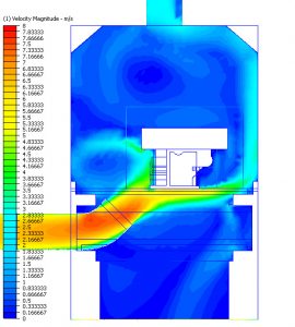
At this point the importance and usefulness of fluid dynamics simulations come into the picture. We can build 3D models of cooling lines and can run simulations of heat transfer features between casting and cooling air. As a result we can examine geometry variations of casting and cooling nozzle positions.
We can quantify the effect of an air nozzle being closer or away from the casting. It is also possible to quantify the benefits of using a different air nozzle shape. We can also have a result on by how much heat transfer coefficient would change if ventilator capacity was increased by 50% (be aware that it will be much less than 50%).
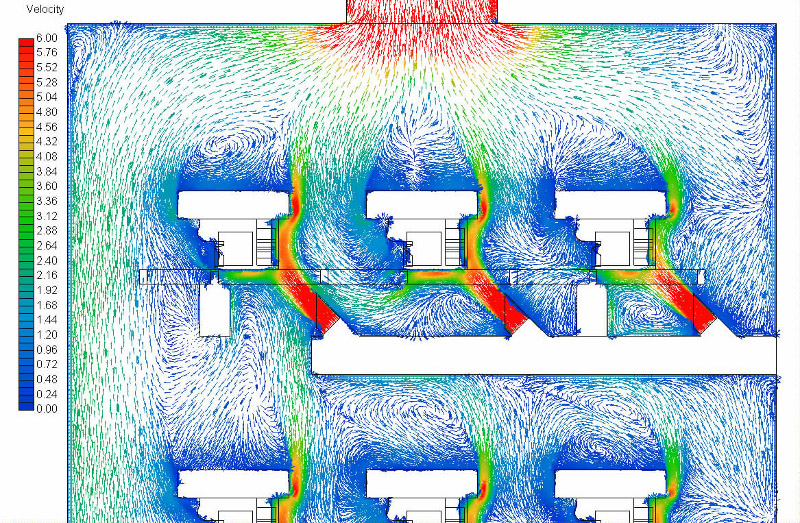
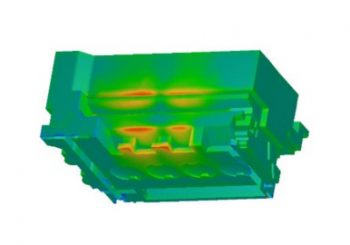
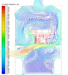
Among many valuable data such a simulation can present in terms of efficient heat transfer, alpha distribution along casting surfaces and heat flux (result of Eq.2) are the most important ones.
![Distribution of heat transfer coefficient [W/m<sup>2</sup>K] on side and top surfaces of casting assembly](https://www.cfdengineering.co.uk/wp-content/uploads/2018/01/34_5_htrc_1.jpg)
![Distribution of heat transfer coefficient [W/m<sup>2</sup>K] on side and bottom surfaces of casting assembly](https://www.cfdengineering.co.uk/wp-content/uploads/2018/01/34_6_htrc_1.jpg)
When simulation is completed for the whole length of the cooling process and heat flux values are available, we have the result of equation (2) for the 80-90 minute long cooling. This can be then compared to the result of equation (1), the heat content of the casting assembly.
It becomes immediately clear if the cooling process is able to take at least the amount of heat content stored in the casting assembly. If heat flux was larger than heat content we could be sure the casting would come out of the cooling line at or below the required 80°C.
CFD modelling can also reveal if design of cooling line needs changing
In case results are not satisfactory, meaning that heat flux is smaller than heat content, then we need to get back to a previous stage of the design process. And either try to reduce heat content (by braking some parts of the cores to expose more metal surface) or to increase efficiency of heat transfer.
This can be done by either decreasing temperature of cooling medium, which could be very costly, or take a look at alpha and increase it over the surfaces of casting assembly. This latter one is much easier than any other method. It is so because increasing velocity of cooling air, resulting higher nozzle speed usually solves the challenge.
But as I mentioned above we can not expect linear correlation between increasing air velocity and increasing heat transfer coefficient. Several cases prove that 50% of ventilator flow rate increase only resulted in 10-12% increase in the average value of heat transfer coefficient.
All of the above can be and should be tested by computer simulations. After this process is done, only the best performing cooling method needs to be tested in the physical world before an investment into a cooling line is made. This simulation aided design method is proven to be effective and brings its cost back faster than any other investment.
Dr. Robert Dul